System Context Diagram

https://ik.imagekit.io/beyondpmf/frameworks/system-context-diagram.png
A System Context Diagram helps define the boundaries of a system, clarifying its scope and relationship to external entities. This visualization aids in establishing a shared understanding of the system's purpose and its alignment within a broader strategic context, which can help prevent unclear direction and lack of market alignment.

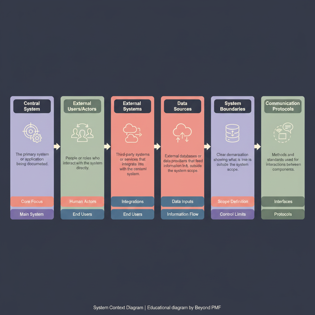
A System Context Diagram is a high-level diagram that defines the boundaries between a system and its environment, showing the entities that interact with it. This diagram is crucial for understanding system interfaces and flows without detailing internal processes. It helps stakeholders understand system interactions and dependencies in a straightforward visual format, aiding in better system design and integration.

Steps / Detailed Description

Identify the system boundary: Define what is considered part of the system and what lies outside its scope. | List external entities: Identify all external entities that interact with the system, such as users, external systems, and data sources. | Define interactions: Map out the interactions between the system and the external entities, including data flow and control signals. | Draw the diagram: Use symbols like rectangles for entities and arrows for interactions to create the diagram. | Review and refine: Validate the diagram with stakeholders and refine as necessary to ensure accuracy and completeness.

Best Practices

Keep the diagram simple and focused on key entities and interactions | Regularly update the diagram as the system evolves | Use standardized symbols and notation for clarity

Pros

Provides clear visualization of system boundaries and interfaces | Facilitates communication among stakeholders | Simplifies complex system interactions into understandable formats

Cons

Lacks detail on internal system processes | Can become cluttered if too many entities are involved | May oversimplify complex interactions

When to Use

During the initial stages of system design | When explaining the system to new stakeholders

When Not to Use

For detailed internal system design | When a high level of detail is necessary for understanding specific processes

Related Frameworks

Lifecycle

Scope

Scope not defined

Maturity Level

Maturity level not specified

Time to Implement

2–4 Weeks
3–6 Months
1–2 Weeks
3–6 Months
1–2 Months
3–6 Months
1–2 Weeks
Less Than 1 Day
1–2 Weeks
Longer Than 6 Months
1–2 Weeks
Longer Than 6 Months
1–2 Weeks
3–6 Months
1–2 Weeks
1–2 Weeks
1–2 Weeks
1–2 Weeks
1–2 Days
1–2 Weeks
1–2 Weeks
1–2 Weeks
1–2 Weeks
1–2 Weeks
1–2 Weeks
3–6 Months
1–2 Weeks
1–2 Weeks
1–2 Weeks
3–6 Months
1–2 Weeks
1–2 Weeks
2–4 Weeks
1–2 Weeks
1–2 Days
1–2 Weeks
Longer Than 6 Months
3–6 Months
Longer Than 6 Months
1–2 Weeks
Longer Than 6 Months
3–6 Months
Less Than 1 Day
3–6 Months
1–2 Months
3–6 Months
Longer Than 6 Months
3–6 Months
Less Than 1 Day
1–2 Weeks
3–6 Months
3–6 Months
1–2 Weeks
3–6 Months
1–2 Weeks
1–2 Weeks
1–2 Days
1–2 Weeks
1–2 Months
Longer Than 6 Months
1–2 Weeks
Longer Than 6 Months
1–2 Weeks
3–6 Months
1–2 Weeks
Less Than 1 Day
1–2 Weeks
3–6 Months
1–2 Weeks
3–6 Months
1–2 Weeks
1–2 Weeks
Longer Than 6 Months
Less Than 1 Day
3–6 Months
Longer Than 6 Months
1–2 Months
1–2 Weeks
Longer Than 6 Months
1–2 Weeks
3–6 Months
1–2 Weeks
1–2 Weeks
3–6 Months
Less Than 1 Day
1–2 Weeks
1–2 Weeks
3–6 Months
3–6 Months
Less Than 1 Day
1–2 Weeks
Longer Than 6 Months
1–2 Months
1–2 Weeks
1–2 Weeks
1–2 Weeks
Longer Than 6 Months

Copyright Information

Autor:
Public Domain
N/A
Publication:
Generic Business Tool